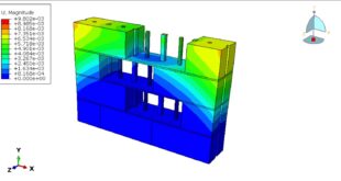
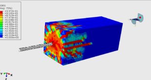
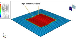
In this tutorial, the Simulation three-point bending test of the UHPC beam reinforced with Jute-Epoxy lamina in Abaqus has been investigated. The UHPC beam is modeled as a three-dimensional solid part. The Jute-Epoxy lamina is modeled as a three-dimensional shell part with four layers. A rigid body shell part is used to apply displacement as a load in the load section. You can see a figure of the assembled parts below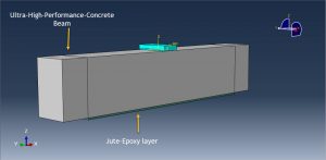
Recently, the use of ultra-high performance concrete (UHPC) for rehabilitation and strengthening of reinforced concrete (RC) beams has been considered by researchers and engineers. The material properties of UHPC, such as super-high tensile and compressive strengths, ductility, and good durability make UHPC attractive for various engineering structures, especially in bridge engineering. The popularly employed Concrete Damaged Plasticity (CDP) model available in ABAQUS was used to model the nonlinear behavior of UHPC in compression and tension. The CDP model can predict the tensile and compressive damage during the analysis. Jute based green composites are emerging materials due to their certain attractive properties like appropriate strength to weight ratio, high damping ratio, low price and corrosion resistance. There is a growing interest for natural and enjoinment friendly materials and the desire to lessen the cost of synthetic fibers which are being utilized generally in synthesis of polymer composites. Numerous scientists have started working on natural fiber composites (i.e., bio composites), because these composites are now widely used in auto-motive industries and in different interior and exterior car parts. To model Just-epoxy lamina, conventional shell with four layers is used. The general static step with some changes in the convergence model to avoid early not convergence is selected. The surface to surface contact with friction as contact property between rigid body and concrete part is used. The ideal contact is selected to define the contact between the UHPC beam and Jute-epoxy lamina. The fixed boundary condition is assigned to the two ends of the beam and displacement to the rigid body. The mesh should be fine to obtain the proper results
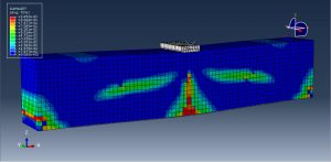
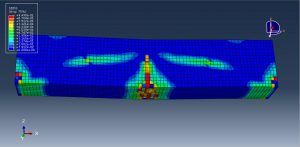
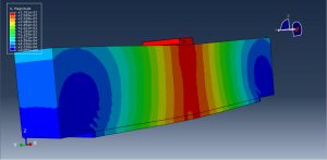
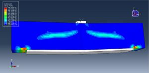
After the simulation, all results such as stress, strain, tensile and compressive damage, force-displacement diagram, and … are available. You can see some figures for the results below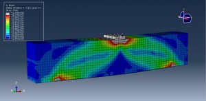
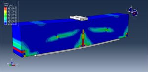
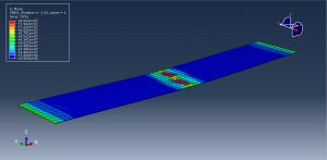
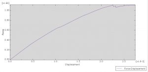
You can provide CAE ,INP,and English video files of this simulation here. The cost of these files is Twenty-Five Euros. you can click on the bellow bottom to beginning process
You can purchase the tutorial through a PayPal account, a Visa, or a Master card, just before payment, send me an email to this address: karampourp@gmail.com
 Abaqus tutorials Abaqus tutorials
