In this tutorial Simulation Shear Capacity of L-Shaped Angle Shear Connectors in Abaqus has been studied.Composite beams are recognized for their high strength and stiffness and reliable structural behaviour. The strength and ductility of shear connectors play a vital role in the design of composite beams. The successful design of shear connectors relies heavily on the existing experimental investigations on the load-slip behaviour of the connector. Many forms of shear connectors are being used in composite beams, however, economical and structural aspects motivates new innovations like C-shaped and L-shaped angle shear connectors. Present knowledge of the load–displacement behaviour and the shear capacity of shear connectors are mainly limited to the data obtained from the experimental push-out or beam tests. Experimental tests are expensive and time-consuming option for such investigations and in some cases can even be impractical.Numerical methods to predict the nonlinear load-slip relationship and the ultimate shear capacity of the shear connectors in composite beams are definitely a valuable option. More so, when the numerical methods are substantiated by accurate experimental results. Finite element (FE) method has become a powerful tool for the numerical analysis of a wide range of engineering problems. An accurate finite element model permits a considerable reduction in the number of experiments needed for the prediction of structural behaviour
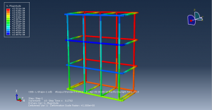
The steel beam,L shape connector and concrete are modeled as three dimensional part. The bar is modeled as wire part. Concrete Damage Plasticity was used for concrete material. For all metal part elastic plastic material is used. You can see a figure of the assembled parts at below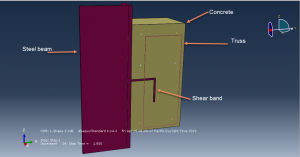
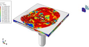
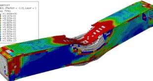
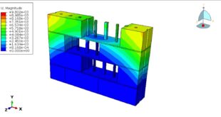
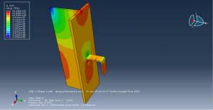
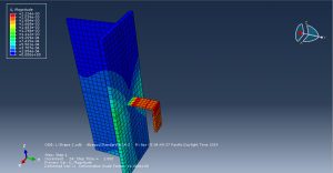
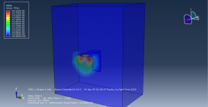
Static solver with surface to surface contact has been implied. Because of symmetry, half of model is consider and symmetry boundary is assigned to the symmetry area. The displacement load is applied to the bottom surface of the concrete part . Fine mesh has a good effect over the accurate results. After the simulation stress,strain and displacement for all parts can be achieve . You can see some figures of the results at below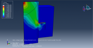
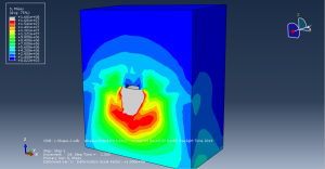
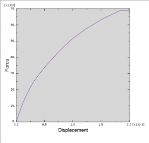
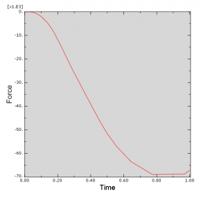
You can provide CAE ,INP,and English video files of this simulation here. The cost of these files is Twenty-Four Euros. you can click on the bellow bottom to beginning process
You can purchase the tutorial through a PayPal account, a Visa, or a Master card, just before payment,send me an email to this address: karampourp@gmail.com
 Abaqus tutorials Abaqus tutorials
