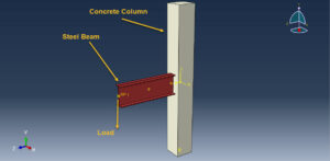
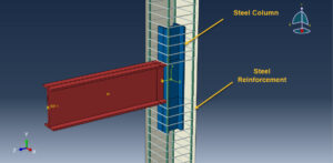
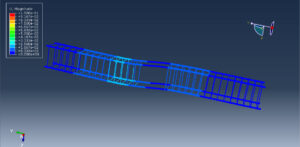
In this tutorial, the Simulation load bearing capacity of a composite joint between a reinforced concrete column and a steel beam in Abaqus has been done. The concrete column is modeled as a three-dimensional solid part. The steel beam and column are modeled as three-dimensional solid parts. The steel bar and strip are modeled as wire parts. You can see figures of the assembled parts below
The reinforced concrete column and steel beam (RCS) frames consist of reinforced concrete (RC) columns and steel (S) beams. This type of structure has several advantages over traditional RC frames or steel frames, including lower cost and structure weight reduction. RC columns offer, superior damping properties to a structure, especially in tall buildings. Indeed, using RC instead of structural steel as columns can result in substantial savings in material cost and an increase in the structural damping and lateral sti ness of the building. The energy dissipation capacity can accordingly be provided through steel beams. In addition, steel floor systems are significantly lighter compared to RC floor systems, leading to substantial reductions in the weight of the building, foundation costs, and inertial forces. To e actively apply RCS frames in a real structure, it is necessary to study the composite connection between steel beams and reinforced concrete columns. Extensive studies have been conducted to study the basic force transfer mechanisms in connection regions and the performance of various joint configurations that enhance the connection performance under seismic excitations. The American Society of Civil Engineers
To model concrete behavior under axial or cyclic loading, the Concrete damaged plasticity is selected. The Concrete damage plasticity material model represents a constitutive model that is based on a combination of the theory of plasticity and the theory of damage mechanics. This material model is often used in solving geotechnical problems due to its realistic description of the mechanical behavior of concrete material. The elastic-plastic model with damage behavior is considered for the steel members
Dynamic explicit or General static steps both are useable. The proper interactions and constraints are applied to the model. The load as displacement with a smooth amplitude is considered. The proper mesh and boundaries are assigned to the parts
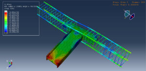
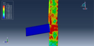
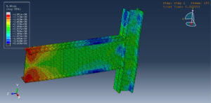
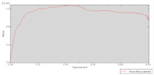
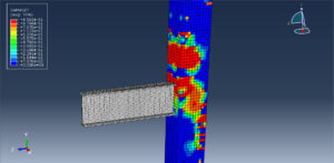
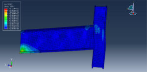
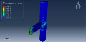
After the simulation, all results such as stress, strain, tensile damage, compression damage, force-displacement diagram, and others are available. You can see some figures for the results below
 Abaqus tutorials Abaqus tutorials
