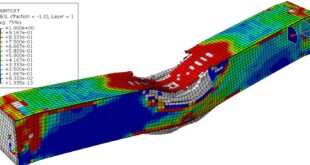
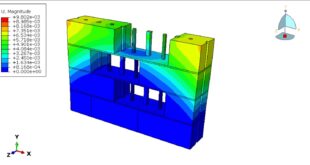
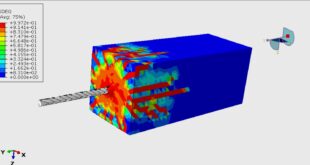
In this tutorial, the Simulation dynamic bending of RC beams strengthened with CFRP rods and Epoxy glue in Abaqus has been done. The concrete beam is modeled as a three-dimensional solid part. The CFRP rod and epoxy glue are modeled as three-dimensional solid parts. The steel bars and strips are modeled as three-dimensional wire parts. Two rigid bodies are created as a hydraulic jack to apply load. You can see a figure of the assembled parts below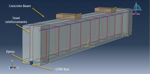
External strengthening of structural members has started as early as 1949 and was called grouted reinforcement or embedded reinforcement in which external steel bars were used to strengthen bridge girders in flexure. Numerous research studies have been conducted over the last two decades on strengthening reinforced concrete (RC) structures using externally bonded fiber-reinforced polymer (FRP) laminates and fabric sheets. Such technology has been implemented in several practical projects all over the world. More recently, Near-Surface Mounted (NSM) FRP reinforcement strengthening techniques have been introduced and employed in practical applications
To model the non-linear behavior of the concrete beam the Concrete Damaged Plasticity model is selected. The model is a continuum, plasticity-based, damage model for concrete. It assumes that the main two failure mechanisms are tensile cracking and compressive crushing of the concrete material. To model the CFRP rod, the elastic model as an engineering constant is used. The steel material with elastic-plastic behavior is considered for the bars and strips. To model epoxy glue behavior, the traction-separation law is selected. During the bending, the epoxy layer will experience damage. Both static and dynamic step can be used, The static step needs a long time to complete the simulation, so the dynamic explicit step is selected. The perfect contact is assumed between epoxy-concrete and epoxy-CFRP rod. The surface to surface contact with friction as contact property is considered between rigid bodies and concrete beam. The steel reinforcements are embedded inside the concrete host. The fixed boundary condition is assigned to the two end sides of the beam. The displacement as a boundary is applied to the two top rigid bodies with a smooth amplitude to apply smooth load. The mesh should be fine to obtain correct results
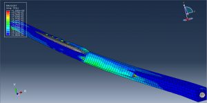
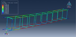
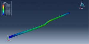
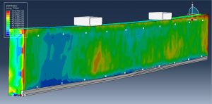
After the simulation, all results such as stress, strain, tensile and compressive damage, cohesive damage, force-displacement diagram, and… are available. You can see some figures for the results below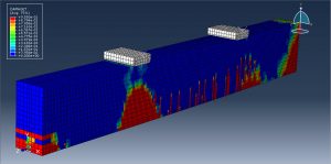
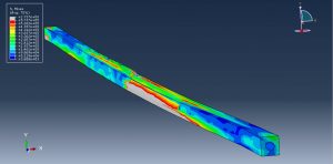
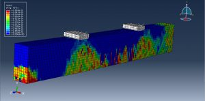
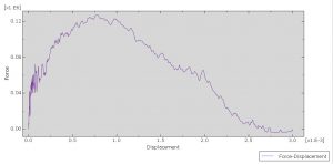
You can provide CAE, INP, and English video files of this simulation here. The cost of these files is Twenty-Nine Euros. you can click on the bellow bottom to beginning the process
You can purchase the tutorial through a PayPal account, a Visa, or a Master card, just before payment, send me an email to this address: karampourp@gmail.com
 Abaqus tutorials Abaqus tutorials
