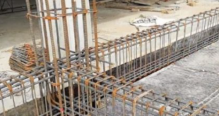
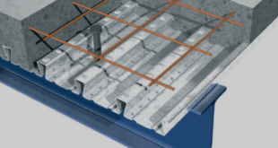
In this tutorial, the Simulation and Analysis of the Seismic Behavior of a Prefabricated Semirigid Steel Frame with X-Shaped Brace in Abaqus has been done. The steel column and beam are modeled as three-dimensional parts. The steel plate as stiffeners and braces are modeled as three-dimensional parts. You can see a figure of the assembled parts below
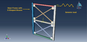
Vigorously promoting and developing steel structure buildings can not only relieve the excess capacity of the steel industry but also promote the greening, industrialization, and informatization of buildings, thus realizing the transformation and upgradation of traditional industries’ development of steel structure houses is the key to promoting the application of steel structures. At present, the connections between beams and columns in steel frames all adopt either rigid connections or hinged connections. However, due to the limited stiffness of the connections used in actual engineering, it is difficult to form an ideal rigid or hinged connection, so a semirigid connection objectively exists. -The design concept of two seismic fortification lines is in line with the modern seismic design concept. -therefore, this type of structure has been widely used in multistory steel-structure buildings. By combining the X-shaped concentrically braced frame with the semirigid steel frame, it is possible to form a prefabricated semirigid steel frame with X-shaped concentric braces. braces can compensate for the weakness of lateral stiffness in the semirigid steel frame and produce satisfactory ductility and energy dissipation capacity, which shows promise for use in engineering applications
The proper material model appropriate with cyclic and seismic loading for the steel material is selected. The general static step with some changes in the convergence model is selected. The weld connection between the column and stiffener plates is used. Contact property as friction is considered. The proper mesh and boundary conditions are assigned to all parts
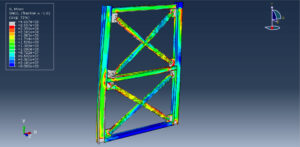
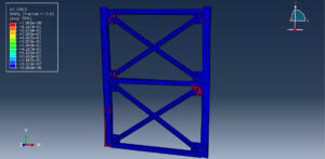
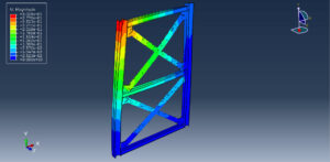
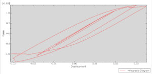
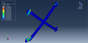
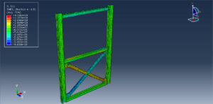
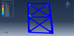
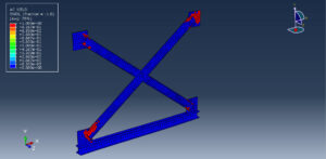
After the simulation in Abaqus, all results such as stress, failure, strain, collapse, Hysteresis diagram, and others are available. You can see some figures for the results below
 Abaqus tutorials Abaqus tutorials
