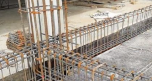
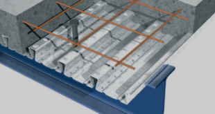
In this tutorial, the Simulation bending test of a steel-concrete(foamed concrete) composite beam in Abaqus has been studied. The foamed concrete ( containing partial cement replacement) is modeled as a three-dimensional solid part. The steel beam is modeled as a three-dimensional shell part. The steel reinforcement is modeled as a three-dimensional wire par and some rigid parts. You can see a figure of the assembled parts below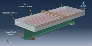
Construction materials using concrete is the primary building element of structures worldwide at present. The application of concrete in civil engineering is vast ranging from construction of bridges, dams to roads and tall buildings. Ever since the development of concrete, many types of concrete have been manufactured. One of them being foamed concrete. It is a type of lightweight concrete whose dry density ranges from 300 to 1800 kg/m 3 which is up to 87% lighter than the normal weight concrete. The Concrete Damaged Plasticity is used to model non linear behavior of the foamed concrete slab. Composite beams with solid or composite slabs have disadvantages in relation to the high operational cost of welding the shear connector on site, the curing time of wet concrete in cold climates and short spans corresponding to the floor height. The steel material with elastic and plastic behavior with ductile damage criterion is selected. The general static step with some changes in the convergence model is used. The surface to surface contact with friction as contact behavior is used to model interaction between concrete slab and rigid bodies. The embedded region constraint is selected for the steel reinforcements which is embedded inside the concrete host. The perfect contact is assumed between steel beam and concrete part. The fixed boundary condition is assigned to two bottom rigid bodies and displacement to the top rigid body. The mesh should be fine to achieve correct results
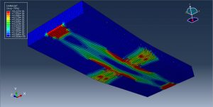
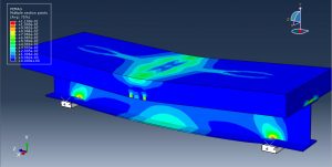
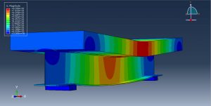
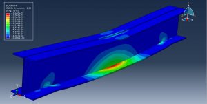
After the simulation, all results such as stress, strain, tensile and compressive damage, ductile damage, fore-displacement diagram, and… are available. You can see some figures for the results below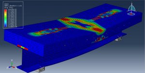
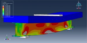
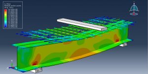
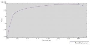
You can provide CAE ,INP,and English video files of this simulation here. The cost of these files is Twenty-Six Euros. you can click on the bellow bottom to beginning process
You can purchase the tutorial through a PayPal account, a Visa, or a Master card, just before payment, send me an email to this address: karampourp@gmail.com
 Abaqus tutorials Abaqus tutorials
