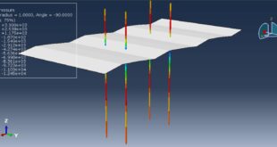
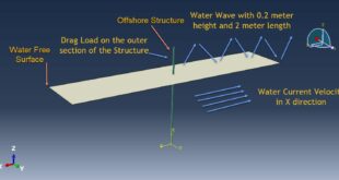
In this tutorial, the Simulation three point bending of a RC beam reinforced with CFRP in Abaqus has been investigated. The concrete beam is modeled as a three-dimensional solid part. The steel bars and strips are modeled as three-dimensional wire parts. The CFRP sheet is modeled as a three-dimensional shell part and one rigid part also is used as a hydraulic jack. You can figures of the assembled parts below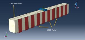
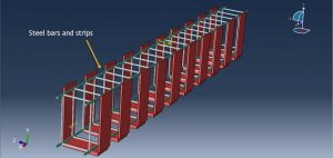
For its strength and durability, reinforced concrete is used in many civil structures, such as bridges and buildings. As with any construction material, Reinforced Concrete (RC) may deteriorate due to many factors such as poor design, selection of low-quality materials, corrosion, and lack of maintenance which ultimately decrease the service life of structures. To maintain and/or extend the service life of RC structures, repair and strengthening are essential. Strengthening is not required only for damaged structures; it is sometimes inevitable for some cases. Examples of such cases include increased safety requirements, updating of the load bearing capacity of buildings, upgrading bridges to accommodate more traffic volume, etc. To model concrete behavior the CDP plasticity model is selected. The steel material with elastic-plastic behavior is used to model bars and strips material. The CFRP is modeled as a conventional shell composite with lamina or engineering constant elasticity and Hashin’s damage criterion. Both static and explicit step is used in two separate simulation. The static step is too difficult to be converge so explicit step with smooth loading rate can be used instead of it because it is so faster. The embedded region constrains is considered for the embedded steel bars and strips inside the concrete host. The perfect contact is assumed between CFRP and concrete beam. The fixed boundary condition is assigned to the two ends of the beam and displacement is assigned to the top rigid body to apply load on the concrete beam surface. The mesh for all parts should be fine to obtain better results
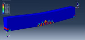
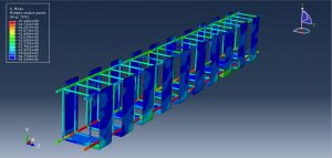
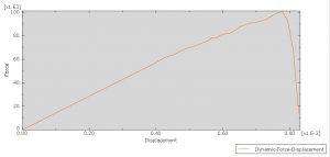
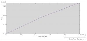
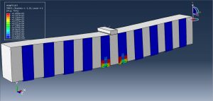
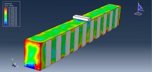
After the simulation, all results from dynamic and static simulation are achievable. You can see some figures for the results below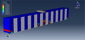
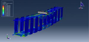
You can provide CAE ,INP,and English video files of this simulation here. The cost of these files is Twenty-Six Euros. you can click on the bellow bottom to beginning process
You can purchase the tutorial through a PayPal account, a Visa, or a Master card, just before payment,send me an email to this address: karampourp@gmail.com
 Abaqus tutorials Abaqus tutorials
