In this tutorial, the Simulation three points bending of High Strength Concrete(HSC) beam in Abaqus has been studied. The primary difference between high-strength concrete and normal-strength concrete relates to the compressive strength that refers to the maximum resistance of a concrete sample to applied pressure. Although there is no precise point of separation between high-strength concrete and normal-strength concrete Manufacture of high-strength concrete involves making optimal use of the basic ingredients that constitute normal-strength concrete. Producers of high-strength concrete know what factors affect compressive strength and know-how to manipulate those factors to achieve the required strength. In addition to selecting a high-quality portland cement, producers optimize aggregates, then optimize the combination of materials by varying the proportions of cement, water, aggregates, and admixtures. The HSC beam is modeled as a three-dimensional solid part. The steel bar is modeled as a three-dimensional wire part. You can see a figure of the assembled parts below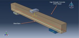
Nonlinear behavior of concrete has been defined using the built-in Concrete Damage Plasticity (CDP) model available in ABAQUS. The four input parameters that are required to fully describe the yield surface and flow rule in the three-dimensional space of stresses include dilation angle (ψ) in degrees, plastic flow potential eccentricity (є), ratio of the strength in the biaxial state to the strength in the uniaxial state (σ bo /σ co ), and the shape factor that defines the yield surface in the deviatoric plane (Kc). The CDP data for HSC is extracted from the reference paper. The steel material with elastic-plastic behavior is used for the bars. The general static step with some changes in the convergence model is used. The surface to surface interaction is used between HSC beam and rigid bodies with friction coefficient as an interaction property. The bars are embedded inside the HSC beam. The fixed boundary condition is implied for the two bottom rigid bodies. The displacement with amplitude is applied for the top rigid body. The mesh should be fine to obtain the correct result
After the simulation, all results such as stress, strain, tensile damage, force-displacement diagram,…. are achievable. You can see some figures for the results below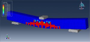
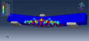
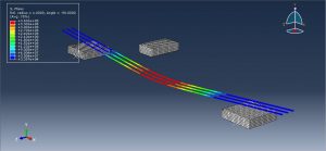
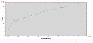
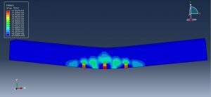
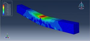
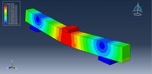
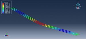
You can provide CAE ,INP,and English video files of this simulation here. The cost of these files is Twenty-Six Euros. you can click on the bellow bottom to beginning process
You can purchase the tutorial through a PayPal account, a Visa, or a Master card, just before payment,send me an email to this address: karampourp@gmail.com
 Abaqus tutorials Abaqus tutorials
